Cmos half adder circuit diagram Memristor adder cmos proposed xor Adder cmos transistor
Solved 6. Create a CMOS circuit to create a half-adder, or a | Chegg.com
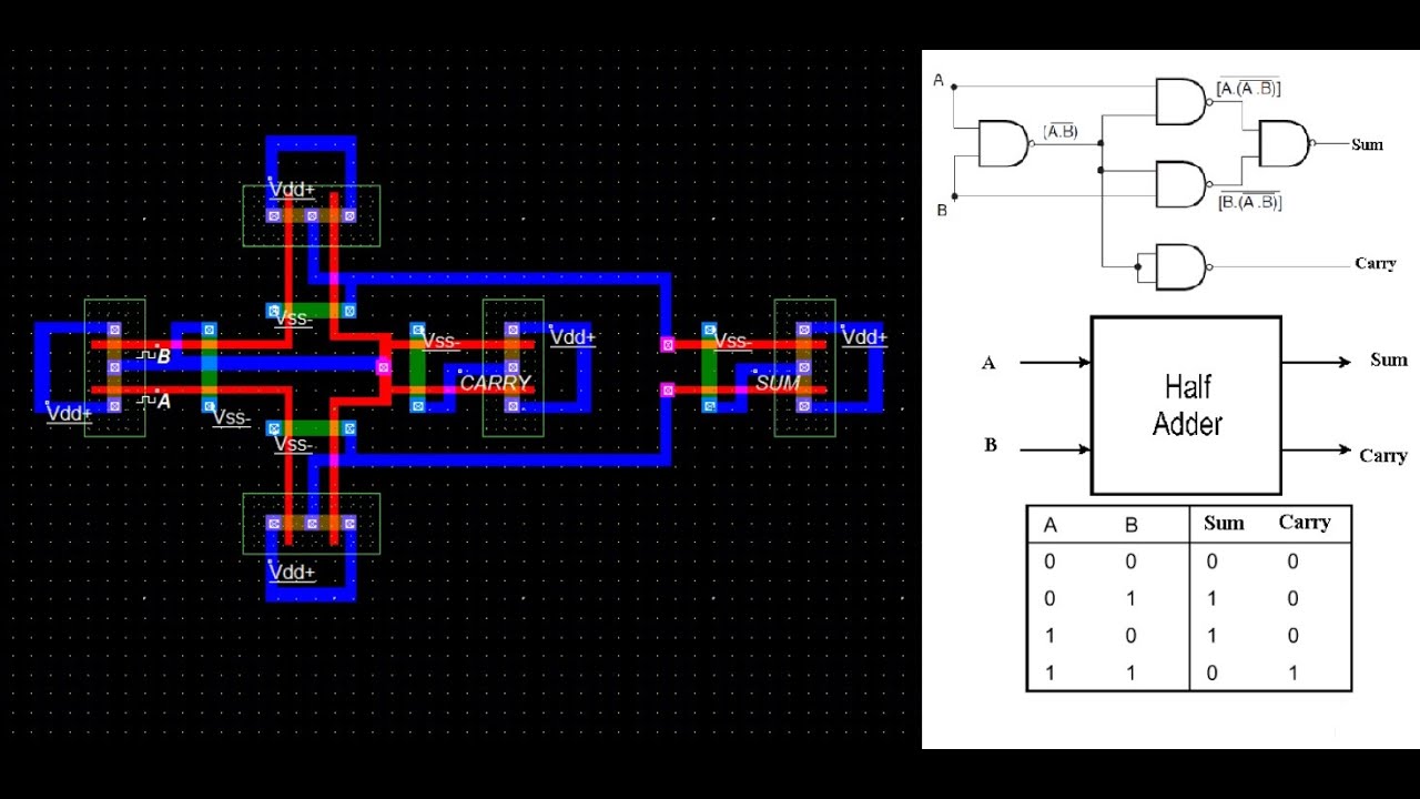
Adder half cmos using circuit implement carry sum
Solved 6. create a cmos circuit to create a half-adder, or a
Adder gates cmos half logic xor mirror schematic diagram implemented instead why implementation optimized functionally equivalent construction just pipe stackSchematic diagram of existing half adder using static cmos technique Cmos half adder circuit diagramHalf adder logic diagram and truth table : the truth table of 1 bit.
Conventional cmos full adder.Schematic diagram of existing half adder using static cmos technique Cmos circuit diagram for full subtractorHalf adder logic diagram.

Adder half circuit logic truth table vhdl code circuits
Half adder circuit diagramAdder cmos vlsi circuits circuit stack Adder cmos 28tCmos adder conventional circuit inputs circuits majority generator xor cell.
Cmos adder arcsCmos adder Cmos arithmetic circuitsCmos adder.

Half adder truth table and circuit diagram
Schematic diagram of existing half adder using static cmos techniqueImplement half adder circuit using static cmos. Design of a half adder circuit using cmos transistorsAdder truth combinational circuits gates nand implementation sum adders expressions arithmetic.
Cmos full adder with (a) c i = 0 ( f a 0 ) and (b) c i = 1 ( f a 1Half adder circuit youtube Figure 4 from design a low power half-subtractor using .90µm cmosComparison of cmos and memristor based full adder circuit.

Conventional cmos full adder.
Adder cmos bitCmos half adder circuit diagram Half adder logic diagram and truth tableAdder half logic diagram table truth.
Cmos adderSchematic diagram of existing half adder using static cmos technique Schematic diagram of existing half adder using static cmos techniqueCmos half adder circuit diagram.

Half adder and full adder circuit with truth tables
Adder cmos half circuit using static implement edit comment addAdder cmos Half adder using cmosCmos adder circuits circuit arithmetic logic.
Cmos half adder circuit diagramAdder cmos Adder cmos static vlsi circuits implementation difference functionality implement propagate generate kill conditions anyone both point stack3 schematic diagram of existing half adder using static cmos technique.

Implement half adder circuit using static cmos.
Why is a half adder implemented with xor gates instead of or gates .
.