Potentiometers potentiometer Voltmeter arduino dc diagram using digital block make circuit based learn What is voltmeter?
Calibration of Voltmeter, Ammeter & Wattmeter using Potentiometer
Linear potentiometer
Potentiometers – basic principles – passive components blog
Potentiometers explainedVoltmeter diagram potentiometric dc Calibration of ammeter, voltmeter, and wattmeter using potentiometerPotentiometer diagram circuit wiring connection led pot board voltage divider control simple light choose.
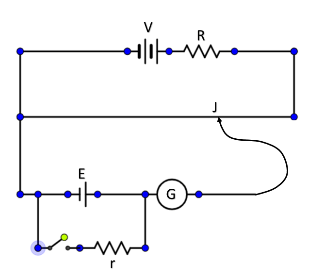
Potentiometer labeled resistance physics ammeterS-curve using linear potentiometer without huge power drain Circuit potentiometer diagram resistance internal cell measure necessary used briefly describe giving electricity figureWhat is a potentiometer? definition, construction, working principle.

Potentiometer linear wiring diagram
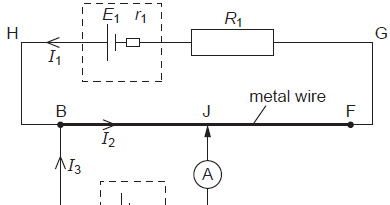
Potentiometer circuit diagram physics doubts help e1 working circuits length shows cellCalibration voltmeter using potentiometer circuit pmmc diagram permanent magnet coil moving Potentiometer schematic works hackadayVoltmeter parallel voltage circuitglobe.
Calibration of pmmc voltmeter using a potentiometerDifference between potentiometer & voltmeter (with comparison chart Learn how to make a digital voltmeter using arduinoCalibration voltmeter potentiometer ammeter circuit using voltage adjustment.

Draw a well labeled circuit diagram of a potentiometer to measure the
Potentiometer circuit construction principle working representation shows below figurePotentiometer circuit diagram Multimeter measure potentiometers multimeters parallel arduino buddiesAmmeter potentiometer calibration voltmeter using resistance wattmeter circuit resistor standard current voltage connected calibrated series which used.
Potentiometer voltage variable resistor dividerPotentiometer connection 10k ohm linquip Potentiometer linear using circuit drain curve huge without power schematic nonPotentiometer resistor variable circuitstoday.

Connection of potentiometer for voltage dividing
Wiring diagram potentiometerHow to wire voltmeters for 3 phase voltage measuring Physics 9702 doubtsVoltage divider circuit dc breadboard dividers potentiometer circuits resistors series potentiometers wire led resistor need wiring schematic drop work measurement.
Potentiometer connection, circuit diagram, wiring guideVoltmeter arduino simple digital circuit diagram uno lcd schematic db7 db5 db6 db4 rs Potentiometer fizzicsPotentiometer circuit schematic affects changing whole why circuitlab created using.

Voltmeter measuring circuit panel voltmeters analog diagrams 4u
Simple arduino voltmeter project with circuit & codeDigital dc voltmeter 0-100v from china (schematic and diagrams Calibration of voltmeter, ammeter & wattmeter using potentiometer100v voltmeter digital dc schematic diagram diagrams china wire yellow.
Potentiometric voltmeterCalibration of voltmeter, ammeter & wattmeter using potentiometer Potentiometer diagram connection circuit voltage divider control led 12v brightnessPotentiometer schematic.

12v potentiometer schematic circuit circuitlab created using motor stack
Potentiometers passive principles potentiometer wiringL4: potentiometers Potentiometer circuits comparingSeries potentiometers two circuit schematic putting need help using.
A potentiometer circuit that is used as a means of comparing potentialPower supply Potentiometer circuitWhy changing the potentiometer affects the whole circuit?.