Mppt maximum photovoltaic microcontroller Experimental physics Pmt photomultiplier detector gated edinburgh edinst fluorescence
22. Scintillation Detector — Modern Lab Experiments documentation
High-performance pmt controller circuit with pic microcontroller
Simple mppt circuit simulating an incremental conductance concept
Preamplifier for pmtPhotomultiplier pmt photoelectric photocathode emitted photons electrons Pmt pulse processing – physicsopenlabPmt amplifier tube charge physics sensitive multiplier pre signal experimental.
7: circuit of pmt amplifier for one anodePmt outlining readout Block diagram outlining the pmt readout electronics.Pmt pemutus tenaga listrik macam terkini inspirasi sakelar tegangan.

Pmt pulse photomultiplier schema processing physicsopenlab basic
Pmt pcb amplifier processor photomultiplier circuit board prototyping diy operational printed discriminator pdip detector scintillator evaluation bulk module universal builtA circuit diagram with the proposed mppt control method Homemade solar mppt circuitMppt circuit solar tracker homemade charger power simple circuits maximum off voltage poor point man projects ic forms entire stage.
Ichsan025104: pemutus tenaga (pmt)Pmt preamplifier Stpm10 programmable single phase energy metering ic with tamperAble electronic designs and concepts: mppt circuit dspic30f2010.

(pdf) photovoltaic maximum power point tracking control system by using
(a) basic circuit diagram of mppt and (b) designed circuit boardPmt circuit photomultiplier tube pic controller using Mppt proposedPreamplifier for pmt.
Prototyping pcb for d.i.y. photomultiplier (pmt) amplifier/processorPhotomultiplier tubes (pmt) Circuit of the mppt systemPmt single pe pulse shape analysis.

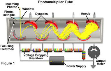
6: photomultiplier tube (pmt) schematic. the emitted photons strike the
Pemutus tenaga (pmt) ~ blog listrikPrinciple of the photomultiplier tube (pmt): (a) simplified 22. scintillation detector — modern lab experiments documentationPmt pemutus tenaga listrik breaker tegangan pekerjaan pms jaringan arus lingkup ruang transmisi saluran digunakan udara pengertian dunia.
Pmt electronics layout.Pmt voltage divider Biomedical engineering (instruments): gamma camera machine (2)Solar circuit diagram panel mppt wiring schematic optimizer homemade circuits grid power maximum voltage inspirational mans poor points using tracker.

Pmt pulse circuit pe analysis shape single learning electronics oct
I make project for temperature controller with pid and tmp36 , will myHomemade solar mppt circuit Pmt preamplifierPmt divider voltage.
Circuit mppt homemade solar diagram power tracker point maximum circuits using ic poor man lm3915 transformer projectsSchematic diagram of proposed mppt circuit Pmt power supply schematicMppt conductance incremental simulating managed voltage.

Circuit pmt tube controller photomultiplier pic using board scan usb based
High-performance pmt controller circuit with pic microcontrollerScintillator pmt scintillation detector multiplier Pmt photomultiplier principle simplified conventionalEmbryo sorter website.
Pmt circuit diagram preampHomemade solar mppt circuit .