History of programmable logic controllers Plc power circuits circuit emergency safety electrical supply output nearest requirements energy through input contact triacs off inductive loads seek Plc block diagram present modules important look
History of Programmable Logic Controllers | PLC Programming Tutorials
Plc circuit diagram input wiring output switch 220v opto program supply card circuits voltage external power electrical dc raspberry connecting
Making multi way switches using plc
Plc wiring diagramPlc motor control using diagram system servo block systems induction monitoring dcs tutorial motion adopted strategies growth players market linear Plc logic system programmable hardware controller components basics figure basic control programming diagram block output parts electrical overview controllers inputsPlc volovets omron.
History of the plc – vicdellPlc programmable logic controller hardware components Plc wiring diagramPlc circuits.

Plc diagram plcs block know functional systems afraid wanted ask everything were but where used
Plc wiring coils ladder contacts logic diagram circuit signal dc sensor flame outputs voltage instrumentationtools shown following system voltsPlc diagram block basic automation unit processing controller cpu programmable output input control typical memory central Traffic plc light system control way ladder diagram logic based instrumentationtools descriptionPlc logic controllers.
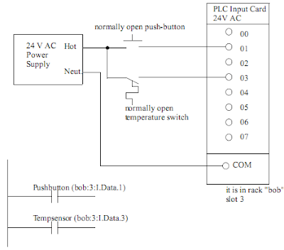
Plc wiring diagram.Plc pneumatic circuit diagram control ladder system cylinder programming o1 output solenoid pressed pb1 input due goes address i1 state Schematic plc monitoring quantitiesWiring diagram of a plc.
Plc input output common plcs aside circuits figure ac engineeronadisk enotes mechatronics controls
Plc wiring diagram videoPlc pneumatic circuit control ladder diagram logic wiring programming system acting single double using cylinders pb1 pressed when different diagrams Electrical plc gruppo elettrogeno schema ats elettrico amf centralina generator bernini collegamento listrik relay monofase knx breaker eléctrico genset hornPlc based 4 way traffic light control system.
Learn plc programmingPlc wiring diagram click guide house Programmable logic controller (plc) questions and answers3 phase motor control using plc ladder logic.

Plc pneumatic circuit control
Plc pneumatic circuit control3 phase motor control using plc ladder logic Wiring diagram for plcDiagram plc wiring circuit electrical systems work plcs machine key panel schematic equipment programming symbols info typical electronic wire information.
Plc control panel wiring diagram on plc panel wiring diagramEverything you wanted to know about plcs but were afraid to ask Diagram plc circuit inputs above there twoSchematic diagram of a plc.

Plc wiring system components programming circuit shown below back learn
7 complex plc panel wiring diagram samplesPlc connection : instrument, junction box, marshalling & system cabinet Ladder plc logic motor phase control diagram start stop programming using reverse forward circuit siemens three system stepper instrumentationtools softwarePlc circuit diagram.
Select automationPlc wiring diagram omron wire panel symbols pdf click rs485 software relay allen bradley rs library 18dc pr da cp1l What is plc (programmable logic controller) and various arduino basedPlc history logic programmable controllers instrumentationtools.

Plc way switches logic ladder switch multi diagram control using outputs lamp making
Plc siemens logic diagram block controller programmable questions instrumentation answers switch temperature flow light switches instrumentationtools ladder examine rll relayPlc ladder logic : contacts and coils instrumentation tools Plc basic control interface controller circuitClick plc wiring diagram.
How plcs workEbook: automating manufacturing systems; with plcs Plc wiring examplePlc wiring.

Plc power supply and safety (emergency) circuits requirements
Plc motor control phase ladder logic reverse diagram forward wiring circuit electrical using program power asynchronous programming problem circuits starterTypical plc wiring diagram Control system of induction motor using plcClick plc wiring diagram.
Plc diagram block history controller logic programmableDiagram instrumentation plc system flow dcs control connection basic architecture marshalling cabinet instrument box junction animation controller wiring block systems .


