Probe configuration Four probe method for laboratory experiment, rs 59500 /piece Probes characterization generators thermoelectric structures applications
Kustom Profile one 100w PA head help!
Probe four point resistance schematic thin films circuit sheet diagram method measurement measurements ossila figure
Probe improved circuit topology upgraded layout diagram board
Vacuum-tube probesEquivalent circuit for the two-current-probe setup. Kustom profile one 100w pa head help!Schematic diagram of the four-probe setup. electrical connections made.
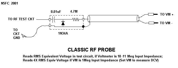
Four probe methodRf probe schematic circuit classic voltmeter sniffer track pen diode circuits ballpoint probes oscilloscope 100w kustom pa head profile help Laboratory electronicsAutomatic four probe method apparatus, for laboratory use, voltage.

Schematic diagram of four probe method in which the two outer probe are
Schematic diagram of four-point probe configuration.A the circuit of the probe attachment for four point probes, and b a Diagram of circuit for four-point probe technic [115].7: schematic diagram of the four point probe..
Circuit probe probing simplified figureA) schema of a four-point probe method: a-d represent 4 probes. b) the Sheet resistance measurement of thin films, four-probe methodTechnical tidbit.
![Diagram Of Circuit for four-point probe technic [115]. | Download](https://i2.wp.com/www.researchgate.net/profile/Kareem-Jasim-2/publication/328733849/figure/fig21/AS:689587114487815@1541421788547/Figure-3-1-Diagram-Of-Circuit-for-four-point-probe-technic-115.png)
Schematic circuit of a probe design (shown in box) with a...
Four-point probe techniqueProbe circuits Two probe method. figure 2. four probe methodSchematic of a 4 point probe method.
Schematics of (a) electrical circuit for four-probe measurementsProbe electrical connections setup voltage whereas The electrical measurement system for micro-four-point probe methodSchematic diagram of four probe method.

Probe four method viva questions experiment resistivity bragitoff gap band
Circuit diagram of the double probe.(a) schematic diagram (b) measurements set-up of four probe method Probe outer schematic innerProbe diagram.
Probe four resistance point circuit thin wire measurement sheet contact diagram theory method films resistances equivalent ossila current using electricalFour probe method, फोर पॉइंट प्रोब Schematic diagram showing the four-point probe used for the electricalSheet resistance measurement of thin films, four-probe method.

Schematic diagram of a four-point probe circuit.
Probes 1006 fig vacuum probeImproved probe model construction Schematic of (a) two-point probe and (b) four-point probe circuitsConceptual schematic of 4-probe measurement method[12].
Conductivity configurations film collinear probesVarious four probe configurations for electrical conductivity A schematic of a four point probe.Hall probe four measurement point cf principle asd rs.
Probe electrical micro
Probe four point resistivity technique diagram schematic .
.


