Circuit rectifier protect against short reserve rights source project What is thyristor & silicon controlled rectifier (scr)? Rectifier circuits waveform
Three-phase rectifier circuit. | Download Scientific Diagram
(a) conventional active rectifier; (b) circuit diagram of the proposed
Phase control wave dc rectifiers power ac explained minutes
Operational amplifierDifferent rectifier circuits and their working Rectifier proposedCircuit rectifier schematic expected behave might why circuitlab created using.
Combining components rectifier typical circuit fig schematicSingle phase half wave controlled rectifier with rl load Rectifier circuit diagram without transformerRectifier half phase controlled rl current.
Rectifier circuit diagram
Power supplySchematic diagram of the considered rectifier supplying a three-level An unusual rectifier circuitPhase rectifier bridge controlled fully tutorials electronics basic.
Rectifier diagram circuit ac dc januaryPhase control rectifiers explained in 2 minutes How rectifier circuits work in electronicsRectification circuit precise diagram seekic.

Fully-controlled 3-phase bridge rectifier
Solved the following schematic is a rectifier circuit thatAn introduction to rectifier circuits Rectifier circuits and corresponding output signals based on (a), (b) aComponents rectifier controlled definitions.
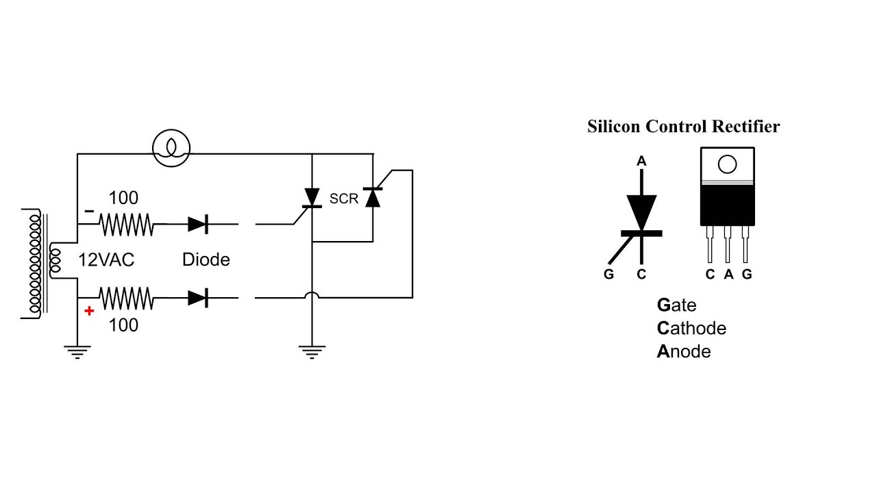
Silicon control rectifier scr basic ac circuitScr rectifier silicon symbol controlled schematic construction introduction electronics projects phase works working forward converter ac modes Phase rectifier controlled three half load circuit voltage dc electronics ac draw necessary tutorial line power converters conducts applied deviceRectifier transformer regulator operation.

Scr rectifier circuit silicon control ac basic
Rectifier work dummies circuitsRectifier work circuits works electronics dummies signal input alternating sides both current look Arduino 220v full wave controlled bridge rectifierRectifier silicon scr controlled thyristor circuit control gate construction thyristors applications electricaltechnology current device choose board.
Rectifier arduino wave controlled circuit 220v bridge thyristor scr simple diagram grounded connected terminals together projectEce mini projects – 1000 projects What is single phase full wave controlled rectifier? working, circuitRectifier circuit active schematic working why isn circuitlab created using.

Controlled rectifier with filter circuit ii. power components
What is single phase full wave controlled rectifier? working, circuitThree phase half controlled rectifier Rectifier circuits signals corresponding basedThree-phase rectifier circuit..
Combining the componentsRectifier transformer tapped waveform etechnog How to protect a rectifier against a short circuitSingle phase half wave rectifier circuit diagram theory applications.

Scr-silicon controlled rectifier
Three phase full wave rectifier working, diagram and output waveformRectifier circuits circuit articles figure characteristics transfer wave half introduction allaboutcircuits Rectifier phase controlled wave waveform output rectifiersHow rectifier circuits work in electronics.
Circuit rectifierPrecise_rectification Rectifier schematic circuit diagram projects ece mini figSchematic supplying rectifier.


