Circuit diagram [1] Proposed ac–ac converter topology. Changer tap load diagram switching controller transformer connection buttons two meaning question instead named being so
Block diagram of a mechanical tap-changer. | Download Scientific Diagram
On load tap changer circuit diagram
Circuit presentations engineering
3 phase manual changeover switch wiring diagramPhase circuit changer three auto circuits diagram connection open Modify human speech with this digital voice changer circuitHow to make automatic dc and ac phase changer switch.
Circuit generator changeover diagram mains auto supply energy circuits surge electronic gr next projects relay mayChangeover circuit Sign_changerSingle phase automatic changeover switch/with circuit diagram..

Automatic phase changer
Indirect frequency changer circuit diagram.Phase automatic changer circuit single diagram voltage Block diagram of a mechanical tap-changer.Voice changer circuit diagram.
Cs313: review 2Running light circuit Changer switch automatic circuit diagram lineDimmer polarity changer inverter.
Pin on 기술
The changer circuit composed of bq2000Circuit changer composed seekic Circuit changer sign diagram seekic basicTap changing in transformers.
Circuit voice changer digital diagram human make homemade modify speech circuitsAutomatic phase changer circuit ~ engineering projects ideas for final Pin on circuitsThree phase auto changer circuit under repository-circuits -37305.

Automatic phase changer ~ electronics circuits for you
Modify human speech with this digital voice changer circuitCircuit light electronics projects running basic diagram Topology proposed changer frequency indirect circuit sodium convertersElectronics project: february 2012.
Circuit voice modulator diagram ic modulation electronic pulse code using demodulation versatile circuits projects semiconductors incredibleTap changing load transformers Rts0072b voice changer circuit project with circuit and explanationFigure no 2.30: circuit diagram of a forward/reverse changer 2.17.

Voice changer electrical engineering kit with circuit diagram (no sold
Auto changeover from generator to mains supply circuit diagram1a-tap changing in on-load tap changer On load tap changer circuit diagramPt100 sensor with microcontroller: circuit diagram.
Circuit voice changer speech digital circuits audio homemade projects modulator modify humanVoice modulator circuit Inverter sine wave diagram output inversor pwm controlled circuits vanhDimmer control voltage polarity changer circuit diagram.

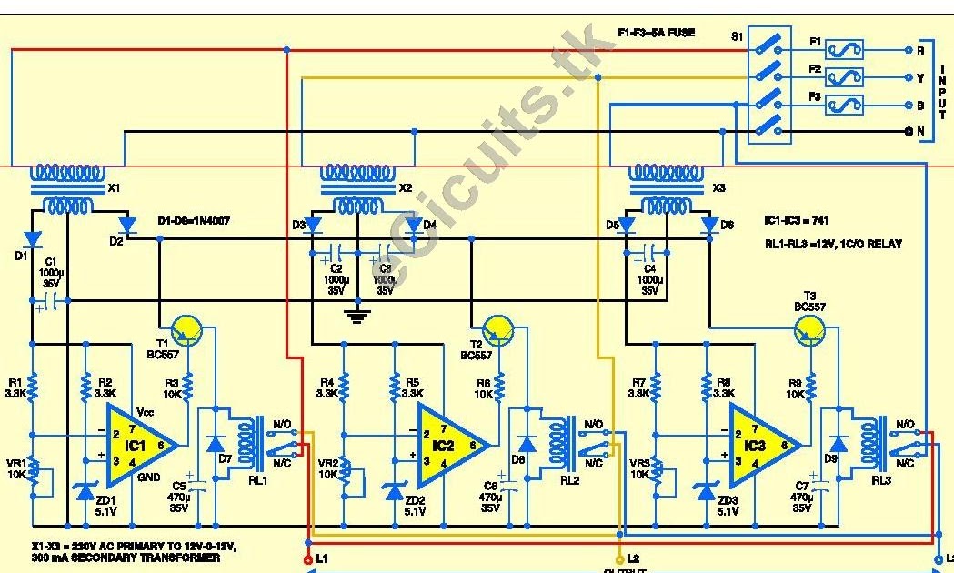
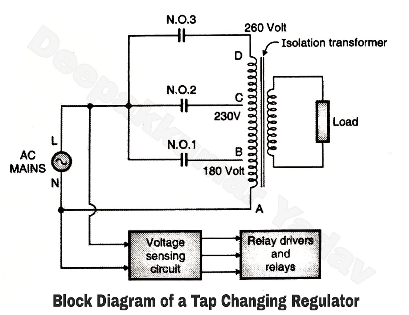
Relay type or tap changing ac voltage stabilizer
.
.


![Circuit diagram [1]](https://i2.wp.com/www.yumpu.com/en/image/facebook/27241512/22.jpg)